Views: 0 Author: Site Editor Publish Time: 2026-07-13 Origin: Site

The growing mandate for decentralized, on-site renewable energy has driven commercial facility managers and developers to consider rooftop wind generation, but the physical realities of urban environments present severe engineering challenges. While a vertical axis wind turbine is marketed as an omnidirectional, low-profile solution for turbulent urban wind, improper specification leads to structural damage, zoning violations, severe noise complaints, and stranded capital. Moving from conceptual interest to procurement requires a rigorous, evidence-based evaluation of site aerodynamics, dynamic structural loads, acoustic regulations, and life-safety compliance. This guide provides the technical framework to determine if a rooftop installation is viable for your specific building envelope and local wind resource.
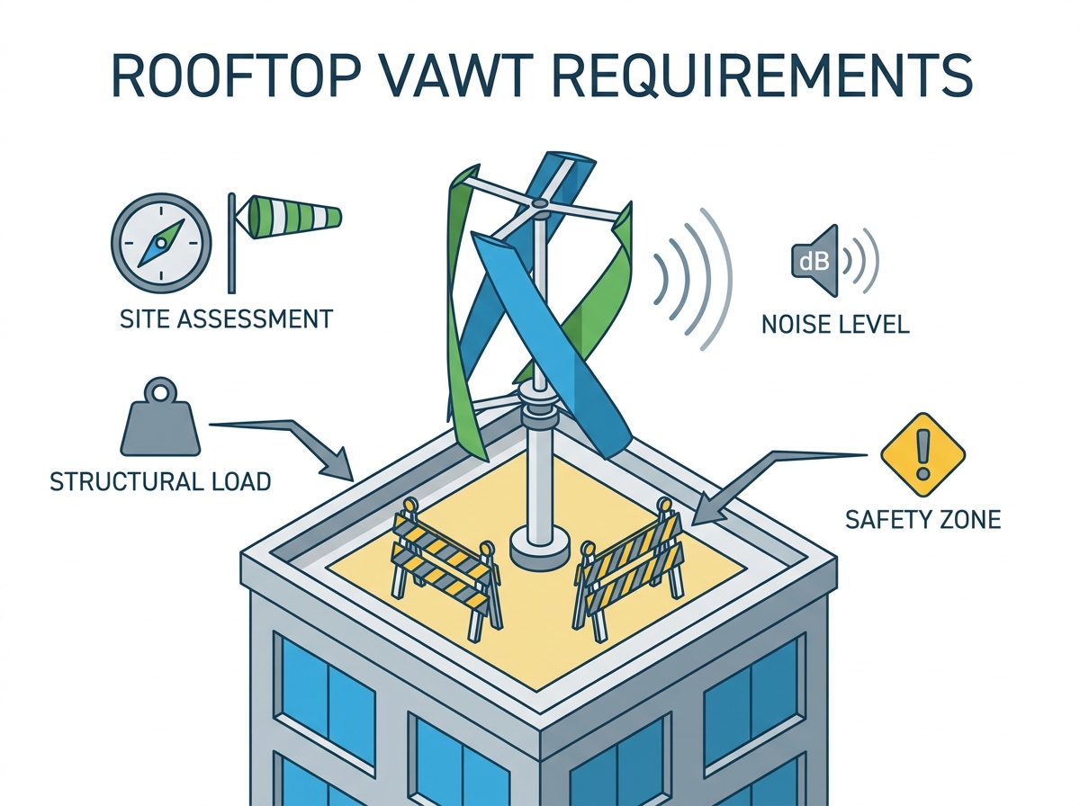
Wind Resource Viability: Rooftop wind is highly turbulent; successful deployment requires tall, unobstructed structures where wind speed consistently exceeds the turbine’s cut-in threshold.
Structural Load Imperatives: Roofs must support not only the static dead weight of the turbine but the severe dynamic and resonant loads generated during high-wind events.
Strict Regulatory Thresholds: Installations often trigger mandatory structural peer reviews (e.g., for sweep areas exceeding specific thresholds like 7m²) and conditional use permits for height variances.
Vibration and Noise Mitigation: Structure-borne vibration is the primary cause of occupant complaints; specialized dampening mounts and acoustic isolation are non-negotiable requirements.
Urban environments create dirty wind. This highly turbulent, multi-directional airflow drastically reduces the actual energy yield compared to manufacturer nameplate ratings. Assessing site viability requires moving past theoretical assumptions and measuring actual kinetic energy potential at the exact installation height. You cannot rely on regional airport weather data; you must measure the microclimate of your specific roof.
Low-rise buildings rarely possess the wind resource necessary for a viable return on energy. The boundary layer effect causes wind speeds to drop significantly closer to ground level due to friction from terrain, trees, and surrounding structures. Evaluating manufacturer claims of stable generation in light, turbulent wind conditions requires heavy skepticism. Actual kinetic energy formulas dictate that power generation increases with the cube of wind speed. A slight drop in wind velocity results in a massive loss of energy output. If the wind speed drops by half, the available power drops by a factor of eight.
Conducting a minimum 6-to-12-month on-site wind study prior to procurement is mandatory. Anemometer testing provides the hard data needed to model realistic energy yields. During this study, you must identify wind shear and wake effects from adjacent high-rises, parapets, or geographical features. These obstructions create localized turbulence zones that can stall blades or cause uneven mechanical wear on the main bearing.
To execute a proper wind resource assessment, follow these field steps:
Mount a sonic anemometer at the exact proposed hub height of the turbine, not just at the roof deck level.
Install a secondary anemometer 10 feet higher to measure vertical wind shear and identify updrafts caused by the building face.
Connect the sensors to a cellular data logger that records wind speed, direction, and turbulence intensity at 10-minute intervals.
Cross-reference the collected data with historical meteorological data to normalize the findings for seasonal variations.
Positioning turbines correctly allows you to capitalize on the building's aerodynamic acceleration. Wind hitting the face of a tall building accelerates as it moves up and over the roof edge, creating a concentrated zone of higher velocity air near the parapet. Placing equipment in this specific shear zone can improve performance, provided the structure can handle the localized stress and the turbulence intensity does not exceed the turbine's mechanical limits.
Clearance requirements dictate placement just as much as wind resource. You must maintain safety distances from HVAC units, exhaust vents, and elevator overruns. Placing a turbine too close to these rooftop elements causes airflow disruption, reducing turbine efficiency and potentially causing mechanical interference with existing building systems. Exhaust vents, in particular, expel dense, conditioned air that can create localized thermal updrafts, further complicating the aerodynamic profile.
Building Height Zone | Aerodynamic Profile | Turbulence Intensity | Viability for Wind Generation |
|---|---|---|---|
1 to 3 Stories | Deep within the urban boundary layer; heavy friction from ground obstacles. | Extremely High | Rarely viable. Wind speeds are generally below the cut-in threshold. |
4 to 10 Stories | Transitional zone; subject to wake effects from neighboring buildings. | Moderate to High | Requires extensive anemometer testing to find clean air pockets. |
11+ Stories | Above the primary urban canopy; access to cleaner, laminar airflow. | Low to Moderate | Highly viable, provided structural and zoning requirements are met. |
Retrofitting an existing roof demands entirely different engineering approaches compared to designing for wind loads in new construction. The building envelope and structural skeleton must absorb continuous, oscillating forces without compromising integrity or waterproofing. You are bolting a dynamic, vibrating machine to a structure designed primarily for static loads.
Static loads represent the dead weight of the turbine, generator, and mounting hardware. Most commercial roofs can handle this static addition with minimal reinforcement, often requiring nothing more than spanning a few structural members to distribute the footprint. However, dynamic loads present the real engineering challenge. Overturning moments, lateral thrust, and aerodynamic drag during extreme weather events exert massive leverage on roof attachments.
When a gust hits the rotor, the mast acts as a lever arm, transferring that horizontal force into a vertical pull-out force on the windward mounting bolts and a crushing compressive force on the leeward side. Resonant frequencies pose a hidden threat. You must ensure the rotational frequency of the turbine does not match the natural frequency of the roof deck. If these frequencies align, harmonic resonance amplifies vibrations, which can cause catastrophic structural failure, sheer bolts, or cause severe fatigue damage to steel I-beams over time.
Choosing the right mounting system involves evaluating the trade-offs in load distribution and waterproofing integrity. Reinforcing structural members becomes necessary when localized stress concentrations exceed the capacity of existing joists, purlins, or concrete decking. You cannot simply bolt a baseplate through a membrane roof into corrugated steel decking and expect it to hold during a gale.
For direct mechanical attachment, the installation sequence must prioritize waterproofing and structural tie-ins:
Core drill through the roofing membrane and insulation down to the primary structural steel or concrete slab.
Weld or bolt custom steel stanchions directly to the primary load-bearing members.
Install pitch pockets or specialized flashing boots around the stanchions to seal the roof penetration.
Fill the pitch pockets with non-shrink grout or pourable structural sealant to prevent water ingress.
Mount the turbine baseplate to the stanchions using vibration-isolating hardware.
Mounting Type | Advantages | Disadvantages | Best Application |
|---|---|---|---|
Ballasted Systems | No roof penetrations; preserves waterproofing membrane; easier to relocate. | Adds massive dead weight; limited resistance to extreme overturning moments. | Concrete decks with high load capacity in moderate wind zones. |
Direct Mechanical Attachment | Maximum structural rigidity; handles severe dynamic loads and lateral thrust. | Requires roof penetrations; higher risk of leaks if flashing fails. | Steel frame or timber roofs in high-wind urban environments. |
Understanding local building codes is non-negotiable. Specific turbine dimensions often trigger mandatory third-party engineering reviews. For example, any unit with a sweep area exceeding 7 square meters typically requires rigorous oversight from a licensed structural engineer who is not affiliated with the manufacturer. The scope of these peer reviews involves a five-pillar validation covering structural integrity, electrical safety, mechanical endurance, noise design, and installation protocols.
The peer review will scrutinize the pull-out strength of the specified anchors, the shear strength of the mounting bolts, and the fatigue life of the mast under continuous cyclical loading. They will also demand proof that the roof structure can handle the combined dead load, live load, wind load, and seismic load with the turbine installed.
Balancing energy generation with the strict acoustic requirements of commercial or residential tenants requires proactive engineering. Ignoring acoustic output leads to tenant disputes, lease terminations, and potential forced decommissioning by municipal authorities. You must engineer the installation to be invisible to the occupants below.
Analyzing the aerodynamic noise generated by blade-wake interactions reveals that real-world performance rarely matches laboratory data. Evaluating manufacturer noise data requires understanding that anechoic chamber ratings do not reflect real-world rooftop performance. Urban turbulence causes irregular blade loading, which generates unpredictable acoustic spikes and low-frequency thrumming that laboratory tests miss.
When a blade passes through the wake of the central mast or another blade, it creates a distinct "whoosh" or thumping sound. In smooth, laminar flow, this sound is consistent and blends into background noise. In turbulent urban air, the varying wind vectors cause the blades to stall and recover rapidly, creating a chaotic acoustic profile that is highly irritating to human hearing.
The transmission pathway for structure-borne vibration starts at the base plate and travels through mounting hardware directly into the building envelope. Low-frequency vibrations resonate through steel and concrete, turning the building itself into a giant speaker. Engineering solutions require specifying elastomeric isolators, spring mounts, and dampening pads to completely decouple the turbine from the structure.
Standard rubber pads are insufficient for heavy rotating machinery. You must specify engineered isolation mounts tuned to the specific operating frequencies of the turbine. These mounts use heavy-duty steel springs housed in neoprene blocks to absorb both high-frequency chatter and low-frequency sway. Additionally, all electrical conduit connecting the turbine to the building must utilize flexible, liquid-tight sections to prevent vibration from traveling down the rigid pipes.
Measuring ambient baseline noise versus operational turbine noise at the property line determines compliance. You must ensure compliance with nighttime decibel limits in mixed-use or residential zoning districts. Municipalities often enforce strict penalties for noise violations, making acoustic isolation a primary design requirement rather than an afterthought.
Before installation, hire an acoustical consultant to measure the existing background noise levels at the property lines during the quietest hours of the night. The turbine's operational noise, combined with the background noise, must not exceed the local statutory limits. If the margins are tight, you may need to program the turbine's inverter to reduce rotor speed or shut down entirely during specific nighttime hours.
Failing to secure permits or violating safety codes presents massive implementation risks. Regulatory compliance dictates the physical parameters of what you can install and where you can place it. You cannot bypass the local authority having jurisdiction.
Navigating municipal height limits starts with understanding the standard 52.5-foot freestanding baseline used in many zoning codes. Exceeding this height to capture better wind resources triggers conditional use permits and zoning variances. Setback requirements from roof edges are equally strict. You must maintain sufficient distance to prevent ice throw or catastrophic blade failure from impacting pedestrians below.
If a blade delaminates or a bearing seizes at high speed, the resulting debris field must be contained entirely within the footprint of the roof. Zoning boards will demand a stamped drawing showing the fall radius and ice throw trajectory based on the turbine's maximum rotational speed. You must prove that no part of the machine can breach the property line under catastrophic failure conditions.
System Wiring and Balance of System components must withstand harsh rooftop environments. Selecting commercial-grade conduit, overcurrent protection, and surge suppression ensures long-term reliability. UV-rated wiring, weatherproof disconnects, and heavy-duty grounding systems are mandatory. Inverter specification requires ensuring compatibility with grid-tied systems and local utility interconnection standards, such as IEEE 1547.
Implementing automatic braking systems, dump loads, and manual disconnects prevents over-speeding during storm events. These fail-safes dissipate excess energy when grid connection is lost or wind speeds exceed safe operational limits.
Electromagnetic Braking: The inverter shorts the generator phases together, using the motor's own magnetic field to stop the rotor.
Mechanical Disk Brakes: A hydraulic or pneumatic caliper clamps down on a rotor disc attached to the main shaft, providing a hard physical stop.
Resistive Dump Loads: Excess electrical energy is diverted into a bank of heavy-duty resistors, converting the kinetic energy into heat to slow the turbine.
Professional installation is mandatory. Standard DIY practices are unviable for commercial-grade rooftop installations. The critical importance of manufacturer torque specifications cannot be overstated; under-torqued bolts back out under vibration, while over-torqued bolts suffer metal fatigue and snap.
Designing safe access routes for routine inspections, such as bearing lubrication and blade torque checks, is an OSHA requirement. Installing permanent tie-off points, guardrails, and ensuring safe working clearances around the rotational sweep area protects maintenance personnel. You must provide a clear, unobstructed path for technicians carrying heavy tools and replacement parts, ensuring they are never forced to unclip their fall protection harnesses while near the roof edge.
Weighing the high upfront capital expenditure and engineering costs against realistic energy yields determines project viability. A vertical axis wind turbine requires careful financial modeling to justify the investment based on actual kilowatt-hour production, not theoretical maximums.
The reality of capacity factors in urban wind dictates that rooftop turbines typically operate at a fraction of their rated capacity. Levelized Cost of Energy calculations for rooftop wind often show higher per-kWh metrics compared to rooftop solar PV. You must base financial models on anemometer data. If the turbine is rated for 5kW at 12 meters per second, but your roof only averages 5 meters per second, your actual output will be a small fraction of that 5kW rating.
Integrating wind generation with existing solar arrays captures nighttime or winter wind resources, balancing seasonal energy production. Solar produces during the day; wind often peaks during passing weather fronts or evening thermal shifts. However, if structural retrofits or zoning battles make the project unfeasible, you must know when to abandon rooftop wind in favor of off-site virtual power purchase agreements or ground-mounted systems.
A rooftop vertical axis wind turbine can support on-site renewable energy goals, but its suitability depends far more on site conditions than on the turbine’s rated output. Urban turbulence, surrounding obstructions, building height, and actual wind speed at the proposed hub position determine whether meaningful energy production is possible.
Even at a promising wind site, the building must safely withstand dead weight, overturning moments, vibration, and repeated dynamic loads. Noise limits, zoning restrictions, electrical protection, roof waterproofing, maintenance access, and fall protection can also influence whether the project is practical.
For this reason, rooftop wind should be evaluated as a complete building-engineering project rather than a standalone equipment purchase. Reliable wind measurements, structural analysis, acoustic planning, and realistic energy-yield estimates are essential before procurement. Where these conditions cannot be satisfied economically, solar, ground-mounted wind, or off-site renewable energy may offer better value.
A: Many municipalities use a standard 52.5-foot baseline for freestanding structures. Exceeding this height typically requires a conditional use permit or zoning variance. Always check local municipal codes, as height restrictions vary heavily by zoning district and proximity to residential areas.
A: Yes. Adding dynamic and static loads to an existing roof requires a structural engineer to verify that the building can handle overturning moments, lateral thrust, and resonant frequencies without compromising structural integrity or waterproofing.
A: Turbines exceeding specific physical dimensions, such as a sweep area of 7 square meters, often trigger mandatory third-party peer reviews. These reviews validate structural, electrical, mechanical, and acoustic design parameters against local building codes.
A: You must decouple the turbine from the building structure using specialized dampening hardware. Specifying elastomeric isolators, spring mounts, and heavy-duty dampening pads prevents low-frequency vibrations from traveling through the baseplate into the building envelope.
A: While they handle multi-directional wind better than horizontal turbines, highly turbulent, light wind lacks the kinetic energy required for significant power generation. Consistent, unobstructed wind speeds are required for a viable return on energy.
A: Grid-tied systems require automatic braking systems, mechanical fail-safes, dump loads, and manual disconnects. These mechanisms safely dissipate excess kinetic energy during severe storms or grid outages to prevent catastrophic mechanical failure and blade delamination.