Views: 0 Author: Site Editor Publish Time: 2026-07-17 Origin: Site

As distributed energy generation expands into urban, off-grid, and turbulent-wind environments, standard horizontal-axis systems frequently fail to meet spatial and aerodynamic constraints. Selecting a vertical axis wind turbine requires navigating complex aerodynamic trade-offs. Engineers and project developers must balance starting torque, power coefficient (Cp), structural fatigue, and acoustic output to ensure project viability and strong returns.
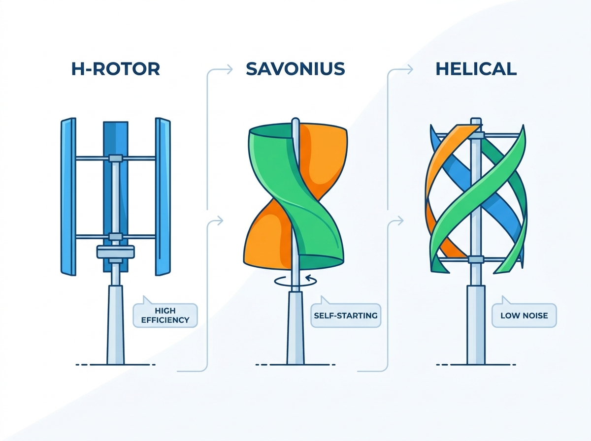
This guide provides a technical evaluation of the three primary turbine architectures: Savonius, H-Rotor (Darrieus), and Helical designs. We compare their operational mechanics, implementation risks, and ideal deployment scenarios. You will gain actionable insights to inform procurement and site planning for your next renewable energy project, ensuring you match the right aerodynamic profile to your specific site conditions.
Savonius rotors utilize drag-based mechanics, offering excellent self-starting capabilities and high torque at low speeds, but yield the lowest overall aerodynamic efficiency.
H-Rotor (Darrieus) designs operate on lift-based aerodynamics, achieving higher power coefficients and rotational speeds, but typically require external power to initiate rotation and face significant centrifugal stress.
Helical (Gorlov/Spiral) configurations mitigate the destructive torque ripple and vibration inherent in straight-bladed designs by distributing aerodynamic loads continuously across the rotational cycle.
Site-specific wind profiling (turbulence intensity, multidirectional flow) is the ultimate determinant of VAWT viability, often outweighing baseline turbine efficiency metrics.
Horizontal-axis wind turbines dominate utility-scale wind farms. They require consistent, unidirectional wind and massive clearance. A vertical architecture offers distinct advantages in restricted environments. These systems feature omnidirectional wind acceptance. They do not require complex yaw mechanisms to track wind direction. You can place the generator and heavy drivetrain components at ground level. This placement drastically simplifies maintenance access and reduces tower structural load requirements.
Engineers rely on advanced analytical models to evaluate performance before deployment. Single Streamtube models provide basic performance estimates. Double-Multiple Streamtube (DMS) models calculate aerodynamic loading across the rotor more accurately. Computational Fluid Dynamics (CFD) simulates complex turbulence visualization. These tools help predict how different blade profiles interact with local wind conditions.
Specific scenarios dictate where these vertical systems outperform horizontal counterparts. High-turbulence urban zones disrupt traditional blades. Restricted airspace or tight physical footprints limit large rotor diameters. Arrays requiring close turbine spacing benefit from differing wake recovery profiles. Vertical turbines pull faster-moving air down into the wake, allowing tighter farm layouts.
Feature | Horizontal-Axis (HAWT) | Vertical-Axis (VAWT) |
|---|---|---|
Wind Acceptance | Unidirectional (requires yaw) | Omnidirectional |
Generator Placement | Nacelle (top of tower) | Ground level |
Turbulence Tolerance | Low | High |
Wake Recovery | Slow (requires wide spacing) | Fast (allows dense arrays) |
Site assessment teams must measure turbulence intensity and wind shear. Standard anemometers often miss rapid directional shifts. Sonic anemometers provide the high-frequency data needed to model vertical turbine performance accurately. You must understand the specific flow dynamics around buildings or natural obstructions to position the rotor effectively.
Foundation design also differs significantly. Horizontal turbines require massive, deep foundations to resist overturning moments from high-altitude thrust. Vertical systems distribute loads differently. The lower center of gravity allows for alternative foundation types, including helical piles or ballast systems, depending on soil conditions and zoning restrictions.
Savonius rotors operate on simple drag-differential mechanics. The wind pushes the concave side of the S-shaped rotor more effectively than the convex side. This differential creates rotation. These turbines operate at a low Tip Speed Ratio (TSR). The TSR typically remains below 1. The blade cannot travel faster than the wind pushing it. This fundamental physics constraint limits their maximum rotational speed.
Classic Savonius designs use simple semi-cylindrical blades. Spiral Savonius geometries twist these blades along the vertical axis. The spiral variation significantly reduces negative drag on the returning blade. It smooths the torque curve throughout the entire rotation. This twisting prevents the dead spots common in standard two-blade drag models.
You should deploy Savonius models in applications requiring high starting torque. They prioritize reliability over raw power output. Ideal use cases include off-grid monitoring stations and remote water pumping. They survive extreme weather environments where high-speed turbines might self-destruct.
Remote telecom base stations requiring continuous trickle charges.
Agricultural water pumping in low-wind regions.
Arctic research stations facing severe icing conditions.
Navigational buoys needing rugged, maintenance-free power.
Engineers must accept significant structural limitations and efficiency trade-offs. The power coefficient typically hovers between 15% and 20%. This sits well below the Betz limit. The high material-to-swept-area ratio impacts manufacturing costs. It also makes large-scale Savonius turbines physically impractical and overly heavy.
Material selection plays a massive role in Savonius construction. Marine-grade aluminum resists corrosion but adds weight. Polycarbonate or fiberglass composites reduce mass but require UV stabilization. You must balance the material density against the required starting torque. Heavier rotors require stronger winds to overcome resting inertia, negating the primary advantage of the drag-based design.
H-Rotor or Darrieus designs utilize straight aerofoil blades to generate lift. The wind flows over the aerofoil, creating a pressure differential. This lift pulls the blade forward. H-Rotors achieve much higher TSRs than drag-based models. They spin faster than the wind itself. This speed translates to significantly better energy extraction efficiencies. Power coefficients can reach up to 35% or 40%.
Pure Darrieus designs suffer from a critical flaw. They cannot self-start in low winds. At zero rotational speed, the angle of attack hits dead bands. The straight aerofoil fails to generate sufficient forward lift to overcome resting inertia. Project developers must integrate motor-assisted starting mechanisms. Grid-tied motoring solutions often provide the initial spin required to catch the wind.
The cycloturbine offers a modified Darrieus design to solve this issue. It features variable-pitch blades. Mechanical or electronic systems dynamically adjust the blades' angle of attack during rotation. This adjustment overcomes the self-starting dead band. It optimizes lift at varying wind speeds, maximizing energy capture across a broader operational range.
Structural engineering challenges remain severe. High rotational speeds generate extreme centrifugal stress. Straight blades experience severe bending moments. The central shaft and bearings endure continuous cyclic stress. Material fatigue risks demand rigorous non-destructive testing during manufacturing and frequent field inspections.
Component | Stress Factor | Mitigation Strategy |
|---|---|---|
Straight Blades | Bending moments from centrifugal force | Carbon fiber reinforcement, strut supports |
Central Shaft | Cyclic lateral loading | Oversized forged steel, maglev bearings |
Blade Connections | Shear stress at attachment points | Titanium fasteners, vibration dampening pads |
Aerodynamic stall presents another operational hurdle. As wind speeds increase, the angle of attack on the retreating blade can exceed critical limits. This causes dynamic stall, shedding vortices that induce severe vibrations. Engineers use advanced aerofoil profiles, like the NACA 0018 or 0021, to delay stall characteristics and broaden the operational envelope.
Helical designs represent a significant evolutionary step. They adapt Darrieus lift principles (Gorlov helical turbine) and Savonius drag principles (spiral drag). Manufacturers twist the blades around the central vertical axis. This geometric shift changes how the turbine interacts with incoming airflow.
The primary engineering advantage lies in continuous blade engagement. A straight blade hits the wind all at once, causing pulsating forces. We call this "torque ripple." Torque ripple causes catastrophic fatigue in straight-bladed H-Rotors. Helical blades eliminate this destructive pulsation. A portion of the twisted aerofoil always maintains an optimal angle of attack. This drastically reduces vibration and increases structural longevity.
These advantages introduce manufacturing complexity. Producing precise helical aerofoils requires advanced composite manufacturing techniques. You cannot simply extrude aluminum for these shapes. This complexity leads to higher upfront capital expenditures. Quality assurance becomes more difficult, requiring laser scanning and precise dynamic balancing.
Installation of helical turbines requires precise alignment. Any deviation from true vertical exacerbates uneven bearing wear. Surveyors use laser transits to ensure the mounting flange is perfectly level. The foundation must resist settling over time, as even a one-degree tilt can introduce destructive harmonics into the rotating assembly.
Maintenance protocols for helical systems focus heavily on surface integrity. The complex curved surfaces are prone to leading-edge erosion from dust and rain. Technicians apply specialized polyurethane tapes or coatings to protect the composite matrix. Regular inspections check for delamination or micro-cracking along the twist axis.
Hybrid systems attempt to combine the best traits of different architectures. A common approach mounts a small Savonius rotor directly on the central shaft of an H-Rotor Darrieus turbine. This creates a nested dual-rotor system.
Operational synergy drives this design. The inner Savonius component provides the necessary starting torque at low wind speeds. It pushes the turbine past the resting inertia. Once the system reaches a sufficient RPM, the outer Darrieus blades take over. The lift-based blades then drive the power generation at higher speeds.
You must carefully evaluate the parasitic drag. At high rotational speeds, the inner drag-based rotor becomes a liability. It creates aerodynamic resistance. This resistance slightly caps the peak efficiency of the lift-based blades. Engineers must assess whether the added mechanical complexity and reduced peak output justify the self-starting benefits.
Control systems for hybrid turbines require sophisticated programming. The inverter must seamlessly transition between the low-speed, high-torque output of the drag rotor and the high-speed, low-torque output of the lift blades. Maximum Power Point Tracking (MPPT) algorithms must account for this dual-mode operation to optimize energy harvesting.
Mechanical coupling between the two rotor types demands robust engineering. The inner and outer rotors experience different aerodynamic forces and thermal expansion rates. Engineers often use elastomeric couplings or specialized slip rings to isolate vibrations and prevent stress fractures at the mounting points.
Selecting the correct architecture depends entirely on your wind resource assessment. Savonius models excel in low, highly turbulent winds. Helical Darrieus models require higher, consistent multidirectional winds to justify their cost. You must map the turbine type directly to your anemometer data.
Scalability and array spacing offer unique opportunities. Adjacent vertical turbines interact aerodynamically. Research indicates that closely spaced, counter-rotating arrays enhance overall farm efficiency. The turbines compress and accelerate airflow between them. This accelerated flow effect boosts the output of downwind units.
Turbine Type | Primary Mechanic | Self-Starting | Efficiency (Cp) | Vibration Level |
|---|---|---|---|---|
Savonius | Drag | Excellent | 15% - 20% | Low |
H-Rotor (Darrieus) | Lift | Poor | 35% - 40% | High (Torque Ripple) |
Helical (Gorlov) | Lift | Moderate | 30% - 35% | Very Low |
Hybrid | Drag + Lift | Good | 25% - 30% | Moderate |
Compare acoustic profiles carefully. Lift models generate a distinct aerodynamic swish. Drag models operate much quieter. Ground-level drivetrains provide massive maintenance advantages across all types. You can service generators without heavy cranes, simplifying zoning compliance in residential or commercial areas. When planning your site, integrating a vertical axis wind turbine requires a thorough review of local noise ordinances and setback requirements.
Grid interconnection standards dictate the electrical components. You must ensure the chosen turbine matches the local utility's voltage and frequency requirements. Anti-islanding protection is mandatory for grid-tied systems. The inverter must automatically disconnect from the grid during power outages to protect utility workers.
Premature main bearing failure presents a massive implementation risk. Asymmetric aerodynamic loading pushes the central shaft unevenly. This constant lateral pressure destroys standard bearings. You must mitigate this via magnetic levitation (maglev) bearings or heavy-duty thrust bearings designed for continuous lateral loads.
Over-speed protection is non-negotiable for lift-based models. Unlike horizontal turbines, vertical turbines cannot pitch their blades out of the wind easily. You must detail robust braking mechanisms. Mechanical disc brakes, aerodynamic spoilers, and electromagnetic braking circuits prevent catastrophic failure during extreme wind events.
Ice accumulation poses a severe threat in cold climates. Ice alters the aerofoil profile, destroying lift and inducing massive imbalances. Active mitigation includes internal blade heating elements or specialized hydrophobic coatings. Passive mitigation involves automated shutdown protocols triggered by temperature and vibration sensors.
Lightning strikes can destroy the control electronics and damage composite blades. Proper grounding is essential. Engineers install lightning rods at the highest point of the turbine structure. Heavy-gauge copper conductors route the strike energy safely to a deep grounding grid, bypassing the sensitive main bearings and generator windings.
Savonius, H-Rotor, and helical vertical axis wind turbines each solve a different set of operating challenges. Savonius designs provide reliable self-starting and strong low-speed torque, while H-Rotors offer higher aerodynamic efficiency when sufficient wind and starting assistance are available. Helical turbines provide a useful middle ground by reducing torque ripple, vibration, and cyclic structural loading.
The most efficient turbine on paper is not automatically the best choice for a real project. Turbulence intensity, average wind speed, starting requirements, acoustic limits, structural capacity, maintenance access, and extreme-weather exposure can all change the final decision.
A reliable selection process therefore begins with site-specific wind data rather than rated power alone. Matching the turbine’s aerodynamic behavior and mechanical demands to the actual installation environment is the most practical way to achieve stable energy output, acceptable maintenance requirements, and long-term project value.
A: Drag-based turbines like the Savonius rely on wind pushing the blade. This results in high starting torque but low rotational speed. Lift-based turbines like the Darrieus use aerofoils to generate lift. This allows them to rotate faster than the wind speed, yielding much higher overall efficiency.
A: At zero rotational speed, the angle of attack of the wind on the straight aerofoil is suboptimal. It does not generate sufficient forward lift to overcome the system's resting mechanical inertia. They require external force to begin spinning.
A: A cycloturbine is a specialized H-Rotor variation with variable-pitch blades. By dynamically adjusting the angle of attack of the blades as they rotate, it generates positive lift even at a standstill. This allows the turbine to self-start without a motor.
A: The twisted blade design ensures that a portion of the aerofoil is always at an optimal angle of attack. This continuous engagement smooths out the aerodynamic forces. It eliminates the cyclical torque pulses and severe vibrations common in straight-bladed designs.
A: The theoretical Betz limit for wind energy extraction is 59.3%. Top-tier lift-based vertical turbines peak around 35% to 40% efficiency. Drag-based models typically max out between 15% and 20% efficiency.
A: Yes. They feature omnidirectional wind acceptance, allowing them to handle chaotic urban turbulence. They produce lower acoustic emissions and have compact footprints. However, structural mounting on buildings requires rigorous vibration analysis.
A: Engineers use Single Streamtube models for basic estimates. They use Double-Multiple Streamtube (DMS) models for detailed aerodynamic loading calculations. Computational Fluid Dynamics (CFD) software provides complex turbulence visualization and precise blade interaction data.