Views: 0 Author: Site Editor Publish Time: 2026-07-06 Origin: Site

Property owners and site engineers face a growing demand for decentralized renewable energy in areas where traditional horizontal turbines fail. Space constraints, strict zoning laws, and highly turbulent wind conditions often render standard wind generation impractical. In these challenging environments, specifying a vertical axis wind turbine provides a viable path to off-grid reliability and energy independence.
However, buyers frequently struggle to separate marketing claims from engineering realities when evaluating these systems. Relying on exaggerated manufacturer specifications leads directly to undersized systems, severe structural damage, and poor energy yields. You cannot simply bolt a turbine to a roof and expect grid-level performance. Success requires a rigorous, data-driven approach.
This guide establishes a strict technical framework for evaluating vertical wind systems. We will base our sizing and selection criteria on actual site wind data, proven aerodynamic design principles, and realistic power curves. By following these engineering standards, you can confidently size and deploy a system anywhere between 500W and 20kW.
Rated Power vs. Actual Yield: Most VAWTs are rated at highly optimistic wind speeds (11–14 m/s); actual energy production depends entirely on the site's average annual wind speed and the turbine's swept area.
Design Dictates Application: Savonius (drag-based) models offer high torque and low cut-in speeds for turbulent areas, while Darrieus (lift-based) models provide higher efficiency but require higher wind speeds to start.
Mounting Realities: Despite marketing claims, residential roof-mounting introduces severe vibration and structural resonance risks; independent tower mounting is almost always required for systems over 1kW, though engineered Building-Integrated Wind Turbines (BIWT) represent a distinct commercial exception.
System Integration: A turbine is only as effective as its charge controller and inverter; matching the alternator's output to the correct grid-tied, hybrid, or off-grid topology is critical for safety and efficiency.
You must evaluate your site conditions before selecting any generation equipment. Vertical turbines solve specific environmental and spatial problems that horizontal models cannot handle. We look for four primary site characteristics when deciding to deploy a vertical system.
The primary advantage of a vertical design is its ability to generate power in turbulent, shifting wind environments without requiring a yaw mechanism to face the wind. Horizontal turbines waste significant kinetic energy constantly hunting for the wind direction. When wind shifts rapidly in valleys, urban perimeters, or heavily forested zones, a horizontal rotor stalls. Vertical models remain stationary on their vertical axis, capturing kinetic energy from any direction instantly. This omnidirectional capability makes them the only logical choice for sites with high turbulence intensity.
Vertical turbines operate at a significantly lower tip-speed ratio (TSR) than horizontal counterparts. The blade tips do not break the sound barrier or create the loud, rhythmic thumping associated with large horizontal blades. This lower rotational speed translates to a drastically lower decibel output. When you install generation equipment near property lines, acoustic emissions dictate permitting success. The compact visual profile and silent operation reduce zoning friction in residential or semi-urban environments.
While vertical turbines boast a smaller rotational footprint, they still require unobstructed airflow to function efficiently. You can install them closer together in multi-turbine arrays because they do not generate the massive, destructive wake turbulence that horizontal turbines produce. However, placing them too close to ground-level obstacles still severely degrades performance. You must map out a clear fetch—the unobstructed distance wind travels before hitting the rotor.
Understanding the physics of wind shear is non-negotiable. Wind speed increases exponentially with height above ground due to surface friction. We call this the boundary layer. Even though vertical turbines handle turbulence better, they still require adequate tower height to access dense, fast-moving air. Installing a turbine too low means it operates in slow, chaotic air, drastically reducing your energy yield. You must calculate the wind shear exponent for your specific terrain to determine the minimum viable tower height.
Install an anemometer at 10 meters above ground level to establish a baseline wind speed.
Install a second anemometer at your proposed hub height (e.g., 20 meters).
Log data in 10-minute intervals for a minimum of 90 days to capture seasonal variations.
Calculate the wind shear exponent using the power law equation to verify the site's vertical wind profile.
Adjust your final tower height specification based on the calculated shear data to ensure the rotor clears the turbulent boundary layer.
Manufacturers utilize different aerodynamic principles to capture kinetic energy. The physical shape of the blade dictates the turbine's starting speed, overall efficiency, and mechanical stress limits. You must match the aerodynamic approach to your site's specific wind profile.
Savonius turbines rely on drag-based operation. They utilize scooped, S-shaped, or overlapping blades to physically catch the wind and push the rotor around the central axis. Because they rely entirely on drag, the blade cannot move faster than the wind pushing it. The tip-speed ratio never exceeds 1.0.
These models feature an exceptionally low cut-in speed, often starting to rotate at just 2 to 3 meters per second. They produce massive starting torque, making them highly reliable in chaotic air. However, their overall aerodynamic efficiency is low, typically capped at 15 to 20 percent of the Betz limit. We specify Savonius designs for micro-generation, highly turbulent environments, and remote applications where extreme durability and self-starting capabilities outweigh the need for maximum power output.
Darrieus turbines utilize aerofoil blades—often in an H-rotor, helical, or eggbeater configuration. These blades generate aerodynamic lift to rotate the central shaft. As wind flows over the curved aerofoil, pressure differences create lift, driving the rotor at speeds significantly faster than the wind itself. The tip-speed ratio often reaches 3.0 or 4.0.
This lift-based mechanism offers much higher efficiency, capturing up to 35 percent of the wind's kinetic energy. They operate at faster rotational speeds, which pairs better with standard alternators. The primary drawback is poor self-starting capability. Darrieus models often require higher wind speeds or a brief motor assist from the inverter to begin spinning. We specify Darrieus turbines for unobstructed sites with consistent, higher-speed winds where maximum energy yield per square meter is the primary goal.
To overcome the limitations of individual designs, engineers develop hybrid systems. These units combine a central Savonius rotor for self-starting torque with outer Darrieus blades for high-speed efficiency. The inner scoops get the rotor moving in low winds, and the outer aerofoils take over as rotational speed increases.
While this broadens the operational wind speed range, it introduces severe trade-offs. You add mechanical complexity, increase the total rotor weight, and raise manufacturing costs. The added weight requires heavier thrust bearings and stronger tower foundations. We only specify hybrids when a site experiences both frequent low-wind days and sustained high-wind events.
Aerodynamic Design | Primary Mechanism | Typical Efficiency | Starting Torque | Best Application Environment |
|---|---|---|---|---|
Savonius | Drag | 15% - 20% | Very High | High turbulence, low average wind speeds, remote telecom. |
Darrieus (H-Rotor) | Lift | 25% - 35% | Low | Clean laminar flow, high average wind speeds, grid-tie. |
Hybrid (Savonius + Darrieus) | Drag & Lift | 20% - 30% | Medium-High | Variable wind sites requiring self-starting and high-end yield. |
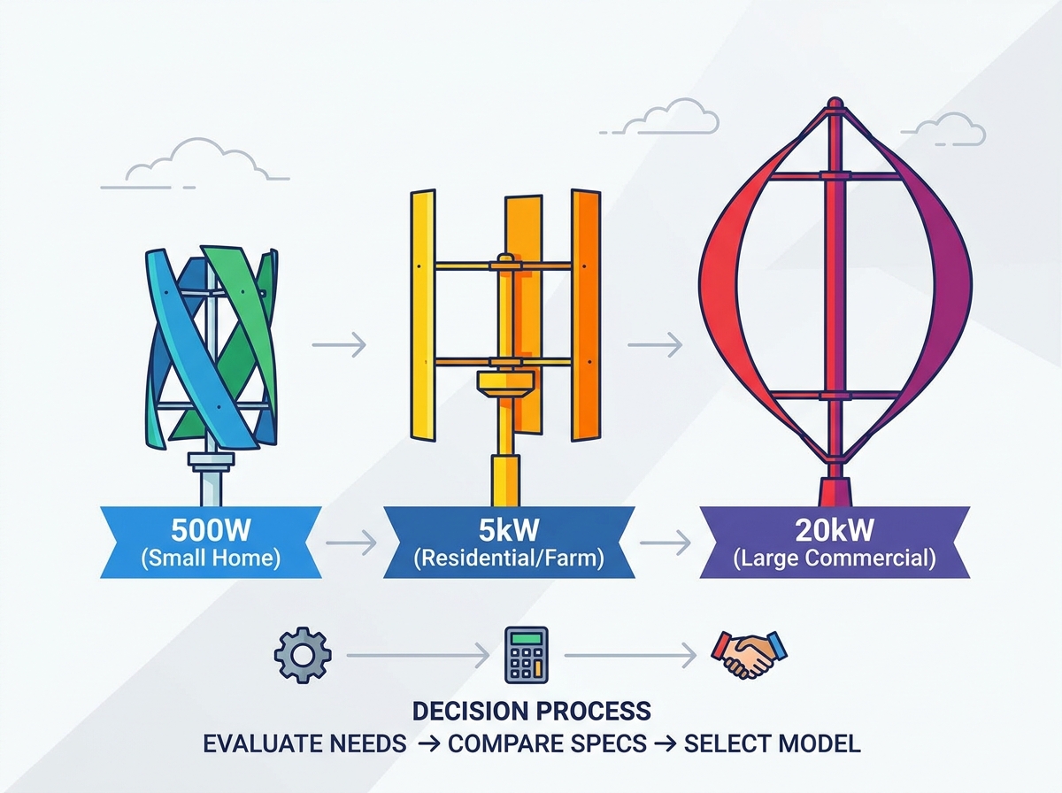
Selecting the correct capacity requires matching the turbine's output to your specific energy consumption profile, battery storage capabilities, and site footprint. We break these systems down into three distinct capacity tiers.
Systems in this tier serve specific, low-draw applications. We use them for battery charging, RVs, remote telecom stations, and supplementary power for off-grid sheds or cabins. When evaluating these micro-turbines, focus on portability, ease of installation, and compatibility with standard 12V, 24V, or 48V charge controllers.
Low-speed start-up performance is critical here. These small turbines are frequently deployed in solar-wind hybrid systems. By pairing a 1kW turbine with a solar array, you leverage complementary seasonal generation profiles. You rely on wind during stormy, overcast winter months and solar during clear summer days. This ensures a steady battery charge year-round without oversizing the battery bank. Pay close attention to DC wire sizing; running 12V or 24V over long distances requires heavy-gauge copper to prevent unacceptable voltage drop.
This mid-range tier targets partial home energy offset, agricultural outbuildings, and grid-tied residential systems. At this scale, the physical dimensions of the swept area become significant. The rotor will likely exceed 3 meters in height and diameter. You must ensure inverter compatibility, deciding between a strict grid-tie setup or a hybrid system with battery backup.
Robust braking systems are mandatory at this tier. You need both automatic electromagnetic braking and manual mechanical lock-outs to protect the larger rotor during storm events. Furthermore, sizing the battery bank capacity correctly is essential. You need enough amp-hours to buffer highly variable wind generation spikes. You must also integrate a dump load—a resistive heating element that bleeds off excess power when the batteries are full and the grid is down, preventing the turbine from over-speeding and destroying itself.
Turbines in the 10kW to 20kW range serve commercial facilities, farms, eco-resorts, and act as primary power generation for large off-grid properties. These systems require three-phase permanent magnet synchronous generators (PMSG) and sophisticated power electronics to rectify the wild AC output into stable DC, then invert it to grid-quality AC.
Installation at this scale involves extensive foundation engineering. You will pour massive reinforced concrete pads, utilize crane-assisted erection, and adhere to strict long-term maintenance intervals. This tier also encompasses Building-Integrated Wind Turbines (BIWT). We assess feasibility for engineered concrete high-rise structures (30 to 35 meters in height) where structural reinforcement and wind tunneling effects can be leveraged safely. You cannot mount a 20kW system on a standard structure; it requires purpose-built structural steel integration.
Manufacturer specification sheets often highlight best-case scenarios recorded in controlled environments. Evaluating a turbine requires looking past marketing metrics to understand its true mechanical and electrical capabilities in the field.
Instruct buyers to ignore the cut-in speed. While the turbine may start rotating at 2 meters per second, the usable power generated at that speed is negligible. It might barely overcome the resistance of the wiring. Instead, focus entirely on the rated speed—the wind velocity required to produce the advertised wattage. Compare this rated speed directly against your site's anemometer data. If a turbine is rated for 5kW at 12 m/s, but your site averages 6 m/s, you will generate a fraction of that power. Survival wind speed indicates the maximum velocity the structure can withstand before catastrophic mechanical failure.
The quality of the alternator dictates system efficiency. Look for coreless Permanent Magnet Synchronous Generators (PMSGs). Standard alternators suffer from cogging torque—the magnetic resistance that prevents the rotor from turning from a dead stop. Coreless designs eliminate the iron core in the stator, significantly reducing this cogging torque. Lower cogging torque allows the turbine to spin freely in lighter winds, increasing overall annual energy production.
Wind energy increases with the cube of wind speed. A storm can destroy an unprotected turbine in seconds. Evaluate the fail-safes rigorously. Require systems that feature automatic electromagnetic braking, which shorts the stator phases to slow the rotor. Require dump load diversion to bleed off excess voltage safely. Finally, demand manual mechanical lock-outs—physical disc brakes or locking pins—to secure the rotor during extreme weather events or routine maintenance.
Blade materials dictate lifespan and performance under cyclic loading. Extruded aluminum offers excellent durability and UV resistance but is heavy, increasing the required starting torque. Carbon fiber provides an exceptional weight-to-strength ratio, improving start-up speeds and efficiency, but costs significantly more. Fiberglass offers a middle ground but can suffer from UV degradation over time. Focus on fatigue limits and how the materials handle constant vibration and lateral wind loads.
Never rely solely on internal manufacturer data. Verify claims using independent third-party certifications such as MCS, Intertek, SGS, or SWCC. Analyze real-world field-test reports rather than laboratory wind-tunnel simulations. Wind tunnels provide smooth, laminar flow. They cannot replicate the chaotic turbulence, rain, and icing conditions of actual installation sites. Demand field data.
A wind turbine is a long-term infrastructure investment. Accurate financial modeling requires calculating all capital outlays and operational expenses over the system's entire operational lifespan.
Do not evaluate the turbine cost in isolation. Calculate the total Capital Expenditure. This includes the turbine hardware, the steel tower structure, the foundation concrete and rebar, specialized power electronics (rectifiers, charge controllers, inverters), heavy equipment rental for installation, and electrical labor. Divide this total project cost by the rated wattage to determine the true CAPEX per watt. This metric allows you to compare the wind project directly against a solar array or a diesel generator.
To compare wind power against grid electricity, calculate the Levelized Cost of Energy. Factor in the expected lifespan, which is typically 15 to 20 years for a well-maintained system. Include scheduled maintenance costs, such as bearing replacements and blade inspections. Divide these lifetime costs by the actual projected annual energy production (AEP) based on your site data. This provides a realistic cost per kilowatt-hour generated over the life of the equipment.
Navigating federal, state, and local renewable energy tax credits dramatically lowers payback periods. Research available grants for agricultural or rural small businesses. Additionally, investigate utility interconnection policies. Net metering agreements allow you to push excess power back to the grid, spinning your meter backward and accelerating your return on investment. Ensure your chosen inverter is certified for grid interconnection in your specific jurisdiction.
Proper planning mitigates the most common failure points associated with vertical wind installations. Field failures rarely stem from aerodynamic flaws; they result from poor mounting, inadequate foundations, and neglected maintenance.
Deconstruct the marketing myth of residential roof-mounted turbines immediately. Wood-frame residential buildings are not designed to handle the structural resonance, dynamic lateral loads, and low-frequency vibration transmission generated by a spinning rotor. Roof mounting leads to cracked drywall, compromised roof trusses, and unbearable interior noise. Contrast this with highly engineered, reinforced concrete commercial BIWT installations on high-rise structures. On a 30-meter commercial building, the massive concrete structure safely absorbs vibrations, and the building's shape can actually funnel wind into the rotor.
Independent towers are mandatory for residential and small commercial systems. Choose between guyed towers or freestanding monopoles. Guyed towers require less steel and smaller foundations but demand a massive footprint for the guy wire anchors. Freestanding monopoles are compact but require massive, deep reinforced concrete foundations to resist overturning moments. The bottom of the rotor must sit at least 30 feet above any obstacle within a 300-foot radius to escape the ground turbulence boundary layer and access clean, laminar airflow.
Before purchasing equipment, navigate local ordinances. Create a strict checklist regarding maximum tower height restrictions. Verify property line setbacks; many jurisdictions require the tower to be set back a distance equal to its total height plus 10 percent. Review strict noise ordinances at the property line. Homeowner Associations frequently prohibit independent towers entirely. Secure all permits before pouring concrete.
The primary point of mechanical failure in vertical designs is the bottom thrust bearing. This bearing supports the entire vertical weight of the rotor while simultaneously handling severe lateral wind loads. Specify systems with accessible grease points and high-load tapered roller bearings. Strictly adhere to scheduled maintenance intervals to prevent catastrophic bearing failure.
Inspect and torque all tower foundation bolts every six months.
Pump fresh synthetic grease into the upper and lower thrust bearings annually.
Test the electromagnetic braking circuit and dump load resistors before the winter storm season.
Inspect blade mounting brackets for stress fractures or loose hardware.
Verify guy wire tension using a tensiometer if utilizing a guyed lattice tower.
If you need assistance evaluating your site data or selecting the correct alternator topology, please contact us for a technical review.
Install a site anemometer at your intended hub height for 3 to 6 months to collect actionable, site-specific wind data.
Consult a licensed structural engineer to evaluate tower foundation requirements, soil bearing capacity, and concrete specifications on your property.
Request full, third-party certified power curve charts from shortlisted manufacturers before making any purchase decision.
Filter out manufacturers making impossible efficiency claims that exceed the theoretical Betz limit of 59.3 percent.
A: It is highly discouraged. Residential wood-frame roofs cannot absorb the low-frequency vibrations, dynamic lateral loads, and structural resonance generated by the spinning rotor. This leads to severe interior noise and potential structural damage to trusses. Independent tower mounting is required for residential applications.
A: Savonius turbines are drag-based, offering high starting torque and low cut-in speeds, making them ideal for turbulent, low-wind areas. Darrieus turbines are lift-based, offering higher aerodynamic efficiency and faster rotational speeds, but require higher, cleaner winds to start spinning.
A: Cut-in speed only indicates when the blades start turning, generating negligible power that barely overcomes electrical resistance. Rated wind speed indicates the velocity required to produce the manufacturer's advertised wattage, which is the metric that actually determines your energy yield.
A: The bottom of the turbine rotor should be mounted at least 30 feet above any obstacle, including trees and buildings, within a 300-foot radius. This ensures the turbine operates above the turbulent ground boundary layer in clean, laminar airflow.
A: The most critical maintenance involves the bottom thrust bearings, which support the rotor's entire weight. Regular greasing, inspecting the electromagnetic braking systems, torquing foundation bolts, and checking tower guy wire tension are required annually.
A: Not necessarily. A pure grid-tie system uses a specialized inverter to push excess power directly to the utility grid without batteries. However, a hybrid system with a battery bank provides backup power during grid outages and buffers highly variable wind generation spikes.