Views: 0 Author: Site Editor Publish Time: 2026-07-24 Origin: Site

Standalone renewable energy systems suffer from inherent intermittency. Solar production drops at night and during winter, while wind patterns fluctuate unpredictably during peak summer days. Attempting to bridge these generation gaps with oversized battery banks requires massive capital and wastes storage potential. Integrating a vertical axis wind turbine with a solar photovoltaic (PV) array offers a balanced generation profile, offsetting seasonal and diurnal dips. However, this hybrid approach introduces complex sizing ratios, charge controller conflicts, and structural integration challenges. Successfully deploying a hybrid solar-wind microgrid requires precise load auditing, site-specific environmental data, and a strict configuration framework. Engineers and installers must ensure both systems operate synergistically without bottlenecking at the inverter or battery bank. This guide details the exact methodologies for sizing, configuring, and maintaining a robust dual-source renewable energy system.
Complementary Generation: A properly sized hybrid system leverages seasonal and diurnal offsets (solar for summer/days, wind for winter/nights) to reduce overall battery capacity requirements.
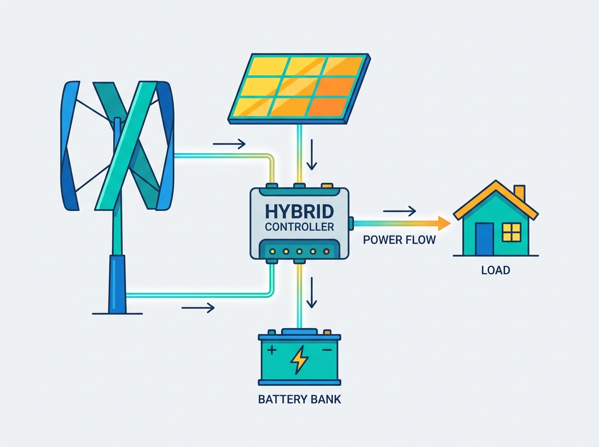
Controller Separation: Solar and wind inputs possess drastically different voltage behaviors; they require dedicated or specialized dual-input charge controllers, alongside mandatory diversion (dump) loads for the turbine.
Site Viability Over Specs: The rated output of a vertical axis wind turbine is irrelevant without laminar (non-turbulent) wind flow, typically requiring installations at least 20 meters (60 feet) above ground obstacles.
Structural Realities: Roof-mounting VAWTs introduces significant vibration and structural fatigue risks; ground-mounted masts are the industry standard for long-term reliability.
Relying on a single renewable source forces deep battery cycling. When solar panels stop producing at sunset, the battery bank carries the entire site load until morning. This daily deep discharge accelerates chemical degradation, causing severe sulfation in lead-acid banks and rapidly consuming the finite cycle life of lithium-iron-phosphate (LiFePO4) cells. Dual sources maintain a higher average state of charge (SoC). Wind energy frequently peaks during nighttime hours or stormy conditions when solar output drops to zero. This complementary generation profile reduces the depth of discharge (DoD). Keeping the battery bank above a 50% SoC rather than draining it to 20% extends the operational lifespan of the storage system by years, directly improving system reliability.
A vertical axis wind turbine provides specific mechanical advantages over horizontal axis wind turbines (HAWT) for hybrid microgrids. VAWTs feature omnidirectional wind acceptance. They do not require a mechanical yaw bearing or tail fin to track wind direction changes. This makes them highly effective in turbulent environments or areas with rapidly shifting wind patterns. They also boast lower cut-in speeds, generating usable power in lighter breezes that would leave a HAWT stationary. Furthermore, their tighter spatial footprint and lower blade tip speed ratio result in quieter operation, making them suitable for residential or light-commercial environments where a massive HAWT would violate zoning ordinances.
Feature | Vertical Axis Wind Turbine (VAWT) | Horizontal Axis Wind Turbine (HAWT) |
|---|---|---|
Wind Direction | Omnidirectional (Accepts wind from 360 degrees) | Directional (Requires yaw mechanism) |
Cut-in Speed | Low (Typically 2-3 m/s) | Moderate to High (Typically 3-5 m/s) |
Noise Level | Low (Lower tip speed ratio) | High (Aerodynamic swoosh from high RPM) |
Maintenance Access | Generator often located at the base | Generator located at the top of the tower |
Space Requirement | Compact vertical footprint | Requires large clearance for blade diameter |
Establishing hard metrics for a hybrid deployment dictates the engineering approach. The primary goal is achieving 95% or higher energy autonomy, minimizing generator run-time or grid reliance. A well-designed system reduces the required battery bank size by 20% to 30% compared to a solar-only installation. Maintaining stable voltage regulation across fluctuating inputs requires precise charge controller programming. Optimization of the overall system coefficient of performance relies on balancing the peak outputs of both generation sources against the daily load profile, ensuring neither source clips excessively due to a full battery bank.
System architecture defines how power flows from generation to storage. DC-coupled systems feed both solar and wind sources into a shared battery bank via dedicated charge controllers. This topology is highly efficient for off-grid and residential applications because it avoids the conversion losses associated with inverting DC to AC and back to DC for storage. AC-coupled systems invert the DC sources to AC first, then synchronize them on a common AC bus. This setup fits large-scale microgrids or grid-tied retrofits where existing AC infrastructure is already in place, allowing grid-tied solar inverters to work alongside AC-output wind turbines.
Hardware requirements differ vastly between grid-tied and off-grid setups. Grid-tied systems require grid-interactive inverters capable of synchronizing with utility frequency and voltage. They mandate strict anti-islanding protection to prevent back-feeding power into the grid during a utility outage, which protects line workers. Off-grid configurations rely entirely on local storage. They require robust hybrid inverters capable of managing heavy surge loads, such as well pumps or compressor motors, without utility support. Off-grid systems also require more aggressive diversion load management, as excess power cannot be sold back to the utility.
A functional hybrid system relies on specific, non-negotiable hardware components. Missing any of these elements compromises system stability and safety.
PV Array: Sized to handle base daytime loads and bulk battery charging.
Wind Turbine: Captures kinetic energy during low-solar periods to float the battery bank.
Blocking Diodes: Prevent reverse current flow between mismatched sources and protect solar panels from nighttime drain.
MPPT Solar Controllers: Maximize solar panel efficiency by tracking the maximum power point of the array.
PWM/MPPT Wind Controllers: Must include boost capability for low-RPM generation and rapid response to wind gusts.
Dump Loads: Resistive heating elements essential for dissipating excess wind energy when batteries are full.
Hybrid Inverters: Manage the conversion of DC battery power to AC load power, often integrating generator auto-start relays.
Battery Management Systems (BMS): Protect lithium storage chemistry from overvoltage, undervoltage, and thermal runaway.
Accurate sizing begins with a strict energy audit. Calculate daily Watt-hour (Wh) requirements by listing all electrical devices, their active power draw, and their daily runtime. Identify peak surge loads (kW) caused by motor startups in well pumps, HVAC compressors, or heavy shop tools. Account for seasonal variations. A site might require 15 kWh per day in the summer for cooling, but only 8 kWh in the winter. Size the inverter based on the maximum simultaneous surge load, and size the generation sources based on the total daily Watt-hour consumption.
Do not rely solely on regional NREL (National Renewable Energy Laboratory) data or airport weather stations. Local topography, tree lines, and adjacent structures drastically alter wind profiles. Install a data-logging anemometer at the exact intended hub height to gather site-specific wind speed data for at least three to six months. Calculate solar insolation hours based on local shading, roof pitch, and latitude. Compare the reliable solar window against the measured wind velocity distribution to determine the optimal generation ratio.
Size the PV array to cover base daytime loads and initial battery charging. Use the standard formula: Total Daily Load / Peak Sun Hours = Required Array Wattage. Factor in system losses, which typically range from 15% to 20% due to wiring resistance, inverter inefficiency, dust accumulation, and temperature coefficients. If a site requires 10,000 Wh per day and receives 4 peak sun hours, the raw requirement is 2,500W. Adding a 20% loss factor pushes the required array size to 3,000W.
Wind power calculation requires specific variables. The wind power equation is P = 0.5 × ρ × A × v³ × Cp. Here, ρ represents air density (roughly 1.225 kg/m³ at sea level), A is the swept area of the turbine in square meters, and v is wind velocity in meters per second. The practical power coefficient (Cp) for a vertical axis wind turbine typically ranges from 0.15 to 0.40. This sits far below the theoretical Betz limit of 0.59. Ignore manufacturer peak ratings, which are often recorded at unrealistic wind speeds like 15 m/s (33 mph). Focus entirely on the power curve at your average local wind speeds, typically between 4 m/s and 7 m/s.
Size the battery bank to safely absorb simultaneous peak outputs from both solar and wind. The maximum charge rate (C-rate) of the battery chemistry dictates how fast it can accept current. Lead-acid batteries generally tolerate a 0.1C to 0.2C charge rate, while LiFePO4 batteries can handle 0.5C to 1.0C. If the combined output of a 5kW solar array and a 2kW wind turbine hits a 400Ah 48V lead-acid bank, the resulting 145 amps exceeds the safe 0.2C limit (80 amps). The batteries will overheat, vent gas, and fail. Calculate the maximum potential amperage from all charge controllers and ensure the battery bank capacity can handle that influx safely.
Wiring solar panels and a wind turbine into the same standard charge controller guarantees immediate system failure. Solar panels output relatively stable voltage, allowing MPPT algorithms to sweep smoothly. Wind turbines produce wildly fluctuating voltage based on instantaneous rotor RPM. Low wind speeds yield low turbine voltage, often dropping below the battery bank's resting voltage, resulting in zero charge current. Specify a wind charge controller with automatic boost-buck functionality. This circuitry steps up the low voltage generated during low-RPM operation to battery-charging levels, capturing kinetic energy that standard controllers would waste.
Diversion loads are mechanically and electrically mandatory for wind systems. When the battery bank reaches 100% SoC, solar controllers simply open the circuit to stop charging. You cannot open the circuit on a wind turbine. Removing the electrical load removes the electromagnetic resistance on the stator. The turbine will free-spin, leading to rapid over-speeding, bearing destruction, and catastrophic blade failure. Dump loads, such as resistive water heating elements or forced-air space heaters, burn off this excess energy. The charge controller utilizes pulse-width modulation (PWM) to route exact amounts of excess current to the dump load, keeping the turbine under load and regulating its RPM.
System monitoring requires tracking the distinct performance of the solar and wind subsystems to verify ROI. Technical requirements include installing separate DC shunts for the solar controller and the wind controller, wiring the anemometer into the data logger, and establishing BMS communication protocols via CAN bus or RS485. DIY and commercial monitoring integrations provide granular data. Installers frequently use microcontrollers like Arduino or ESP32 for custom sensor arrays. Set up Wi-Fi telemetry to log data into central software platforms such as Victron Venus OS, Home Assistant, or Node-RED. This allows operators to track real-time wind speed against turbine output and monitor dump load activation.
Wind shear and ground friction destroy turbine efficiency. The boundary layer near the earth's surface is filled with turbulent, swirling air caused by trees, buildings, and topography. The industry guideline dictates that a turbine must be mounted at least 20 meters (60 feet) high. Alternatively, mount it 10 meters above any obstacle within a 100-meter radius. This elevation is required to access smooth, laminar flow. Turbulent wind near the ground causes erratic blade rotation, induces severe mechanical stress on the vertical shaft, and drastically reduces power output.
Ignore the marketing claims regarding easy roof-mounted turbines. Roof-mounting introduces severe risks of harmonic resonance. As the turbine spins, it generates low-frequency vibrations. Structural vibration transmission travels down the mast and directly into the roof trusses, creating unbearable humming noises inside the living space. Roof fatigue over time leads to compromised weatherproofing, leaks, and structural failure. Ground-mounted masts, anchored in engineered concrete footings with proper rebar reinforcement, are the industry standard for long-term reliability, safety, and noise mitigation.
Navigating local regulations is a primary installation hurdle. Research local noise ordinances, setback requirements, and height restrictions before purchasing hardware. Many municipalities restrict residential towers to 35 feet without a special variance. Grid-interconnection agreements require UL-certified equipment, rapid shutdown compliance, and professional electrical sign-offs. Homeowner associations frequently block visible turbine installations entirely, requiring careful negotiation, presentation of decibel data, or specific zoning variances.
Hybrid systems require strict mechanical and electrical maintenance checklists to prevent premature failure.
Grease main shaft bearings every 6 to 12 months using manufacturer-specified synthetic lubricants.
Inspect blade weldments and composite surfaces for microfractures caused by centrifugal stress and UV degradation.
Torque-test all mounting bolts on the mast, guy wires, and turbine assembly to spec using a calibrated torque wrench.
Verify mechanical and electrical brake operation by manually triggering an overspeed fault.
Check all heavy-gauge electrical connections for corrosion, loose lugs, and thermal damage using an infrared thermometer.
Test the manual short-circuit emergency brake switch to ensure it stops the rotor completely.
Verify dump load resistance values with a multimeter to ensure the heating elements have not burned out.
Evaluate the cost per watt of adding solar capacity versus the cost per watt of adding wind capacity. Solar panels are mass-produced, highly affordable, and require minimal mounting hardware. Wind turbines require heavy steel masts, specialized boost controllers, diversion loads, and expensive concrete foundations. The initial CAPEX for wind is significantly higher per watt. However, the value of wind lies in its generation timing. Generating 1 kWh of power at 2:00 AM during a winter storm is vastly more valuable than generating 1 kWh at noon in July, as it directly reduces the need for massive, expensive battery banks.
Contrast the solid-state reliability of solar panels with the mechanical wear-and-tear of turbines. Solar panels routinely last 25 to 30 years with zero moving parts, requiring only occasional cleaning. Wind turbines operate in harsh, dynamic environments. They require regular bearing replacements, blade inspections, slip-ring maintenance, and controller updates. Factor these ongoing Operations and Maintenance (O&M) costs into the long-term ROI calculations. A turbine that requires a $500 bearing replacement every five years alters the payback period significantly.
Determine when it is more economically viable to simply over-size the solar array and battery bank rather than introducing the complexity of a wind turbine. If the site has poor wind resources (average wind speeds below 4 m/s), spending capital on extra LiFePO4 batteries and ground-mounted solar panels yields a better return. Only proceed with a hybrid system if local anemometer data proves consistent, reliable generation during low-solar periods. Scalability in solar is linear; scalability in wind requires exponential increases in tower height and swept area.
A hybrid system combining solar and wind generation provides a highly resilient engineering solution for off-grid applications, high-latitude locations, and critical infrastructure. This resilience depends entirely on verified wind resources, strict adherence to electrical configuration rules, and proper mechanical installation.
Execute a comprehensive energy audit to define exact daily load profiles and peak surge requirements before selecting inverter sizes.
Install a data-logging anemometer at the proposed turbine hub height and record wind speeds for 3 to 6 months to verify site viability.
Purchase hybrid-capable inverters and dedicated wind charge controllers that explicitly support PWM diversion loads.
Pour engineered concrete footings for a ground-mounted mast, strictly avoiding roof-mounted installations to prevent structural damage.
Consult with a certified hybrid systems engineer to validate electrical topologies, wire sizing, and battery C-rate limits.
A: Yes, you can connect them to the same battery bank, but they must use completely separate charge controllers. Wiring both sources into a single controller causes voltage tracking conflicts, destroys MPPT algorithms, and leads to immediate system failure.
A: There is no universal ratio. The balance depends entirely on site-specific weather data. Typically, solar handles the bulk of the daytime load, while the wind turbine is sized to maintain battery charge overnight and during heavy winter months.
A: You must install a dedicated wind charge controller equipped with a diversion load. When the battery bank reaches full capacity, the controller redirects excess wind current to a resistive dump load, such as a water heater, preventing overcharging while keeping the turbine under mechanical load.
A: To access smooth, laminar wind flow and avoid ground-level turbulence, the turbine should be mounted at least 20 meters (60 feet) above the ground, or 10 meters above any obstacle within a 100-meter radius.
A: No. Solar MPPT controllers cannot handle the rapid voltage spikes or the free-spinning risks associated with wind turbines. Wind requires specific controllers that manage rapid RPM changes, provide low-voltage boost functions, and integrate diversion loads.
A: Roof-mounting is highly discouraged. The harmonic resonance and structural vibrations generated by the spinning turbine transmit directly into the framing, causing severe noise issues and long-term fatigue damage to the roof trusses.